|
|
|
|
Omnidirectional plane-wave destruction |
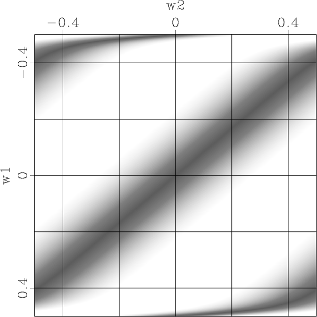
We show the magnitude responses of the
infinite impulse response (IIR)
omnidirectional PWD (OPWD)
![]() when
when ![]() in
Figure 4d-f.
Compared with the ideal responses in
Figure 2,
it has good approximations for all the three dip angles
in most of the frequency band.
There are distortions in the high frequency bands,
due to
phase approximation errors in
in
Figure 4d-f.
Compared with the ideal responses in
Figure 2,
it has good approximations for all the three dip angles
in most of the frequency band.
There are distortions in the high frequency bands,
due to
phase approximation errors in
![]() for high frequencies.
They are not significant in practice,
because the frequency band of seismic data is temporally limited.
for high frequencies.
They are not significant in practice,
because the frequency band of seismic data is temporally limited.


|
|---|
|
liir20,liir50,liir80,oiir20,oiir50,oiir80
Figure 4. Magnitude responses of the IIR implementation of LPWD |
|
|
When
![]() or
or ![]() ,
the omnidirectional PWD has a low-frequency response similar to that
of line-interpolating PWD (LPWD)
shown in Figure 4a-b.
When
,
the omnidirectional PWD has a low-frequency response similar to that
of line-interpolating PWD (LPWD)
shown in Figure 4a-b.
When
![]() , the LPWD has
aliasing in low-frequency bands
(Figure 4c),
while the OPWD exhibits a more desirable low-frequency response
(Figure 4f).
, the LPWD has
aliasing in low-frequency bands
(Figure 4c),
while the OPWD exhibits a more desirable low-frequency response
(Figure 4f).
Following Fomel (2002),
the IIR LPWD
![]() can be approximated by the following
finite impulse response (FIR) filter:
can be approximated by the following
finite impulse response (FIR) filter:
| (16) |
Similarly, the IIR OPWD filter
![]() can also be approximated by an FIR implementation:
can also be approximated by an FIR implementation:


|
|---|
|
lfir20,lfir50,lfir80,ofir20,ofir50,ofir80
Figure 5. Magnitude response of the FIR approximation of LPWD |
|
|
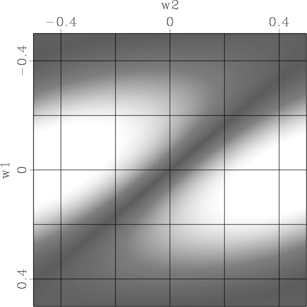
The frequency responses of these two FIR approximations
are shown in Figure 5.
Similar to the IIR implementation,
the FIR OPWD (Figure 5d-f)
can obtain an expected low-frequency response
for all three dip angles.
While the FIR LPWD cannot obtain a good low-frequency response
when
![]() (Figure 5c).
Compared with the IIR implementations,
the FIR approximations of both LPWD and OPWD have
less desirable high-frequency responses.
(Figure 5c).
Compared with the IIR implementations,
the FIR approximations of both LPWD and OPWD have
less desirable high-frequency responses.
|
|
|
|
Omnidirectional plane-wave destruction |