|
 |
 |
 | A transversely isotropic medium with a tilted
symmetry axis normal to the reflector |  |
![[pdf]](icons/pdf.png) |
Next: Extended imaging condition
Up: A transversely isotropic medium
Previous: Introduction
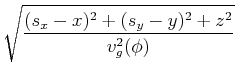
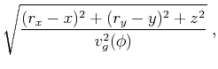
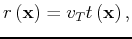
To appreciate the simplification attained from this constraint , we
initially restrict our discussions to a homogeneous medium. In this
case, the zero-offset isochron, which is representative of the equal
traveltime surface, is spherical in shape, equivalent to the isotropic
medium isochron, with a radius governed by the velocity in the tilt
direction,  , as follows:
 |
(1) |
where  is the time along the wavefront and
 represents space coordinates. This convenient assertion is only true if
we constrain the tilt axis to the direction normal to the reflector
dip, and thus the group velocity equals the phase velocity equals the
velocity along the tilt. Figure 1(a) shows a schematic plot of the
zero-offset isochron with two representative examples of tilt
direction that are constrained to be orthogonal to the isochron
surface. 2Though such a medium do not physically exist, it is assumed here in the context of a process, and thus what matters
is the local action of the isochron on the reflection, which is similar to the isotropic case.
represents space coordinates. This convenient assertion is only true if
we constrain the tilt axis to the direction normal to the reflector
dip, and thus the group velocity equals the phase velocity equals the
velocity along the tilt. Figure 1(a) shows a schematic plot of the
zero-offset isochron with two representative examples of tilt
direction that are constrained to be orthogonal to the isochron
surface. 2Though such a medium do not physically exist, it is assumed here in the context of a process, and thus what matters
is the local action of the isochron on the reflection, which is similar to the isotropic case.
For non zero-offset case, the traveltime isochron is constrained by the
double-square-root (DSR) formula (Claerbout, 1995). Thus, the
total traveltime,
, is a combination of traveltimes from the source
 located at (
 ,
, ), and the receiver
  located at
(
located at
( ,
, ) to an image point in the subsurface at location
  and is
given by the expression
and is
given by the expression
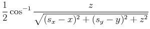
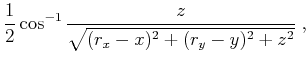
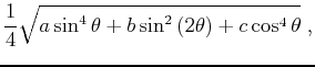
where  is the group velocity as a function of group angle
 . From Figure 1(b), and considering, for simplicity, that the incident and reflected rays are confined to the vertical plane,
can be evaluated geometrically
as follows:
. From Figure 1(b), and considering, for simplicity, that the incident and reflected rays are confined to the vertical plane,
can be evaluated geometrically
as follows:
otherwise we have to project the angles to the plane that constrains the incident and reflected rays. However, evaluating  2
in complex media is complicated with no
closed-form representation. An alternative is to rely on the phase angle by using plane waves and the Fourier decomposition.
2
in complex media is complicated with no
closed-form representation. An alternative is to rely on the phase angle by using plane waves and the Fourier decomposition.
If we reformulate the DSR equation in terms of changes in time, and
thus, focus on the plane-wave relation we end up with the following
DSR formula:
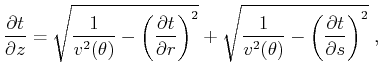 |
(4) |
where now  is the phase velocity and has a closed form
representation in terms of the phase angle
is the phase velocity and has a closed form
representation in terms of the phase angle  given by the
acoustic approximation (Alkhalifah, 1998) as follows:
given by the
acoustic approximation (Alkhalifah, 1998) as follows:
where
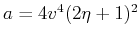 ,
,
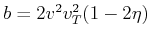 ,
,  ,
is the NMO velocity with respect to the tilted symmetry axis, and
,
is the NMO velocity with respect to the tilted symmetry axis, and
 is the anisotropy parameter relating the NMO velocity to the
velocity normal to the tilt. The angle
in equation 4 is
measured from the tilt direction and will also be given by the angle
gather as part of the process of downward continuation
as we will see later.
is the anisotropy parameter relating the NMO velocity to the
velocity normal to the tilt. The angle
in equation 4 is
measured from the tilt direction and will also be given by the angle
gather as part of the process of downward continuation
as we will see later.
Thus, in the non-zero offset case the isochron depends on angle, but
it is a single angle for both source and receiver rays and we do not
have to worry about relating the two angles, as is the case in VTI and
general TTI media. This provides us with analytical relations for
plane waves at the reflection point. In this case, both the source and
receiver waves have the same wave group velocity
that differs along the
non-zero offset isochron. In fact, for the zero-dip part of the
isochron the reflection angle is at its maximum reducing to zero for a
vertical reflector, as seen in Figure 1(b).
Next, we formulate the extended imaging condition, necessary for angle-gather development, for the DTI model. As shown in this section, angle gathers are also necessary for an explicit formulation of
downward continuation in a DTI model.
|
|---|
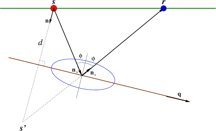
Reflection
Figure 2. A schematic plot of the reflection
geometry for a 2tilted transversely isotropic TTI medium with a tilt in the dip direction. The
incident and reflection angles are the same given by the group angle
. 2Here,  and
and  correspond, respectively, to the
source and receiver locations,
correspond, respectively, to the
source and receiver locations,  is the distance between the source and the reflector in the direction given by unit vector
 normal to the reflector with direction described by unit vector
 , and
, and  and
and  are, respectively, the unit vector directions for each of the source and receiver rays with ray angle
measured from the normal to the reflector.
are, respectively, the unit vector directions for each of the source and receiver rays with ray angle
measured from the normal to the reflector.
|
|---|
![[png]](icons/viewmag.png) ![[xfig]](icons/xfig.png)
|
|---|
|
|
|
|
| A transversely isotropic medium with a tilted
symmetry axis normal to the reflector | |
|
Next: Extended imaging condition
Up: A transversely isotropic medium
Previous: Introduction
2013-04-02